Colours | Sizes and shapes
| Resistor
value | LEDs in series
| LED data |
Flashing |
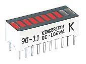
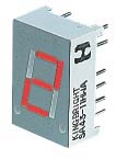
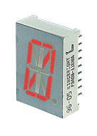
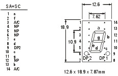
Displays
Example: ![]() Circuit symbol:
Circuit symbol: ![]()
 LEDs must be connected the correct way round, the diagram
may be labelled a or + for anode and k or - for
cathode (yes, it really is k, not c, for cathode!). The cathode is the short
lead and there may be a slight flat on the body of round LEDs. If you can see
inside the LED the cathode is the larger electrode (but this is not an official
identification method).
LEDs must be connected the correct way round, the diagram
may be labelled a or + for anode and k or - for
cathode (yes, it really is k, not c, for cathode!). The cathode is the short
lead and there may be a slight flat on the body of round LEDs. If you can see
inside the LED the cathode is the larger electrode (but this is not an official
identification method).
LEDs can be damaged by heat when soldering, but the risk is small unless you
are very slow. No special precautions are needed for soldering most LEDs.
LEDs must have a resistor in series to limit the current to a safe value, for
quick testing purposes a 1k![]() resistor is
suitable for most LEDs if your supply voltage is 12V or less. Remember to
connect the LED the correct way round!
resistor is
suitable for most LEDs if your supply voltage is 12V or less. Remember to
connect the LED the correct way round!
For an accurate value please see Calculating an
LED resistor value below.
 LEDs are available in red, orange, amber, yellow, green, blue and
white. Blue and white LEDs are much more expensive than the other colours.
LEDs are available in red, orange, amber, yellow, green, blue and
white. Blue and white LEDs are much more expensive than the other colours.
The colour of an LED is determined by the semiconductor material, not by the
colouring of the 'package' (the plastic body). LEDs of all colours are available
in uncoloured packages which may be diffused (milky) or clear (often described
as 'water clear'). The coloured packages are also available as diffused (the
standard type) or transparent.
 The most popular type of tri-colour LED has a red and a green LED
combined in one package with three leads. They are called tri-colour because
mixed red and green light appears to be yellow and this is produced when both
the red and green LEDs are on.
The most popular type of tri-colour LED has a red and a green LED
combined in one package with three leads. They are called tri-colour because
mixed red and green light appears to be yellow and this is produced when both
the red and green LEDs are on.
The diagram shows the construction of a tri-colour LED. Note the different
lengths of the three leads. The centre lead (k) is the common cathode for both
LEDs, the outer leads (a1 and a2) are the anodes to the LEDs allowing each one
to be lit separately, or both together to give the third colour.
 |
|
|
Round cross-section LEDs are frequently used and they are very easy to install on boxes by drilling a hole of the LED diameter, adding a spot of glue will help to hold the LED if necessary. LED clips are also available to secure LEDs in holes. Other cross-section shapes include square, rectangular and triangular.
As well as a variety of colours, sizes and shapes, LEDs also vary in their
viewing angle. This tells you how much the beam of light spreads out. Standard
LEDs have a viewing angle of 60° but others have a narrow beam of 30° or less.
 An LED must have a resistor connected in series to limit the
current through the LED, otherwise it will burn out almost instantly.
An LED must have a resistor connected in series to limit the
current through the LED, otherwise it will burn out almost instantly.
The resistor value, R is given by:
| R = (VS - VL) / I |
VS = supply voltage
VL = LED voltage (usually 2V,
but 4V for blue and white LEDs)
I = LED current (e.g. 20mA), this must be
less than the maximum permitted
If the calculated value is not available choose the nearest standard resistor value which is greater, so that the current will be a little less than you chose. In fact you may wish to choose a greater resistor value to reduce the current (to increase battery life for example) but this will make the LED less bright.
So R = (VS - VL) / I
For more information on the calculations please see the Ohm's Law page.
 If you wish to have several LEDs on at the same time it may be
possible to connect them in series. This prolongs battery life by lighting
several LEDs with the same current as just one LED.
If you wish to have several LEDs on at the same time it may be
possible to connect them in series. This prolongs battery life by lighting
several LEDs with the same current as just one LED.
All the LEDs connected in series pass the same current so it is best if they are all the same type. The power supply must have sufficient voltage to provide about 2V for each LED (4V for blue and white) plus at least another 2V for the resistor. To work out a value for the resistor you must add up all the LED voltages and use this for VL.
Example calculations:
A red, a yellow and a green LED in series
need a supply voltage of at least
3 × 2V + 2V = 8V, so a 9V battery would be
ideal.
VL = 2V + 2V + 2V = 6V (the three LED voltages added up).
If the supply voltage VS is 9V and the current I must be 15mA =
0.015A,
Resistor R = (VS - VL) / I = (9 - 6) / 0.015 =
3 / 0.015 = 200![]() ,
,
so
choose R = 220![]() (the nearest
standard value which is greater).
(the nearest
standard value which is greater).
 Connecting several LEDs in parallel with just one resistor shared
between them is generally not a good idea.
Connecting several LEDs in parallel with just one resistor shared
between them is generally not a good idea.
If the LEDs require slightly different voltages only the lowest voltage LED
will light and it may be destroyed by the larger current flowing through it.
Although identical LEDs can be successfully connected in parallel with one
resistor this rarely offers any useful benefit because resistors are very cheap
and the current used is the same as connecting the LEDs individually. If LEDs are in parallel each one should have its own resistor.
The table below shows typical technical data for some 5mm diameter round LEDs with diffused packages (plastic bodies). Only three columns are important and these are shown in bold. Please see below for explanations of the quantities.
| Type | Colour | IF max. |
VF typ. |
VF max. |
VR max. |
Luminous intensity |
Viewing angle |
Wavelength |
| Standard | Red | 30mA | 1.7V | 2.1V | 5V | 5mcd @ 10mA | 60° | 660nm |
| Standard | Bright red | 30mA | 2.0V | 2.5V | 5V | 80mcd @ 10mA | 60° | 625nm |
| Standard | Yellow | 30mA | 2.1V | 2.5V | 5V | 32mcd @ 10mA | 60° | 590nm |
| Standard | Green | 25mA | 2.2V | 2.5V | 5V | 32mcd @ 10mA | 60° | 565nm |
| High intensity | Blue | 30mA | 4.5V | 5.5V | 5V | 60mcd @ 20mA | 50° | 430nm |
| Super bright | Red | 30mA | 1.85V | 2.5V | 5V | 500mcd @ 20mA | 60° | 660nm |
| Low current | Red | 30mA | 1.7V | 2.0V | 5V | 5mcd @ 2mA | 60° | 625nm |
| IF max. | Maximum forward current, forward just means with the LED connected correctly. |
| VF typ. | Typical forward voltage, VL in the LED resistor
calculation. This is about 2V, except for blue and white LEDs for which it is about 4V. |
| VF max. | Maximum forward voltage. |
| VR max. | Maximum reverse voltage You can ignore this for LEDs connected the correct way round. |
| Luminous intensity | Brightness of the LED at the given current, mcd = millicandela. |
| Viewing angle | Standard LEDs have a viewing angle of 60°, others emit a narrower beam of about 30°. |
| Wavelength | The peak wavelength of the light emitted, this determines the colour
of the LED. nm = nanometre. |
 |
 |
 |
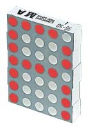 |
| Bargraph | 7-segment | Starburst | Dot matrix |
 |