Soldering Techniques
Overview
Soldering is accomplished
by quickly heating the metal parts to be joined, and then applying a flux and a
solder to the mating surfaces. The finished solder joint metallurgically bonds
the parts - forming an excellent electrical connection between wires and a
strong mechanical joint between the metal parts. Heat is supplied with a
soldering iron or other means. The flux is a chemical cleaner which prepares the
hot surfaces for the molten solder. The solder is a low melting point alloy of
non ferrous metals.
Solder and Flux
Solder is a metal or
metallic alloy used, when melted, to join metallic surfaces together. The most
common alloy is some combination of tin and lead. Certain tin-lead alloys have a
lower melting point than the parent metals by themselves. The most common alloys
used for electronics work are 60/40 and 63/37. The chart below shows the
differences in melting points of some common solder alloys.
| Tin/Lead | Melting Point |
| 40/60 | 460 degrees F (230 degrees C) |
| 50/50 418 degrees F | (214 degrees C) |
| 60/40 374 degrees F | (190 degrees C) |
| 63/37 364 degrees F | (183 degrees C) |
| 95/5 434 degrees F | (224 degrees C) |
Most soldering jobs can be done with fluxcored solder (solder wire with the flux in a "core") when the surfaces to be joined are already clean or can be cleaned of rust, dirt and grease. Flux can also be applied by other means. Flux only cleans oxides off the surfaces to be soldered. It does not remove dirt, soot, oils, silicone, etc.
Base Material
The base material in a
solder connection consists of the component lead and the plated circuit traces
on the printed circuit board. The mass, composition, and cleanliness of the base
material all determine the ability of the solder to flow and adhere properly
(wet) and provide a reliable connection.
If the base material has surface contamination, this action prevents the solder from wetting along the surface of the lead or board material. Component leads are usually protected by a surface finish. The surface finishes can vary from plated tin to a solder - dipped coating. Plating does not provide the same protection that solder coating does because of the porosity of the plated finish.

The Correct Way to
Solder
Some Reasons for Unwettability
The Soldering Iron Tip
The soldering
iron tip transfers thermal energy from the heater to the solder connection. In
most soldering iron tips, the base metal is copper or some copper alloy because
of its excellent thermal conductivity. A tip's conductivity determines how fast
thermal energy can be sent from the heater to the connection.
Both geometric shape and size (mass) of the soldering iron tip affect the tip's performance. The tip's characteristics and the heating capability of the heater determines the efficiency of the soldering system. The length and size of the tip determines heat flow capability while the actual shape establishes how well heat is transferred from the tip to the connection.
There are various plating processes used in making soldering iron tips. These plating operations increase the life of the tip. The figure below illustrates the two types of plating techniques used for soldering iron tips. One technique uses a nickel plate over the copper. Then an iron electroplate goes over the nickel. The iron and the nickel create a barrier between the copper base material and tin used in the solder alloy. The barrier material prevents the copper and tin from mixing together. Nickel-chrome plating on the rear of the tip prevents solder from adhering to the back portion of the tip (which could cause difficulty in tip removal) and provides a controlled wetted area on the iron tip. Another plating technique is similar but omits the nickel electroless plating, leaving the iron to act as the barrier metal.

What is a Weller® Tip - How Does It
Work?
A Weller tip is made of a copper corewhich is
electro-plated with iron to extend the life of the tip. The non-working end of
the tip is plated with nickel for protection against corrosion and then chrome
plated to prevent the solder from adhering except where desired. The wettable
part is tin covered.
The task of the tip is to store the heat which is produced by the heating element and to conduct a maximum amount of this heat to the working surface of the tip.
For fast and optimal heat transfer to the solder joint the tip mass should be as large as possible. When choosing a soldering tip always select the largest possible diameter and shortest reach. Use fine-point long reach tips only where access to the work piece is difficult.
How to Care For Your Tip
Because of
the electro-plating Weller tips should never be filed or ground. Weller offers a
large range of tips and there should be no need for individual shaping by the
operator. If there is a need for a specific tip shape which is not in our
standard range we can usually provide this on a special order basis.
Although Weller tips have a standard pretinnng (solder coating) and are ready for use, we recommend you pretin the tip with fresh solder when heating it up the first time. Any oxide covering will then disappear. Tip life is prolonged when mildly activated rosin fluxes are selected rather than water soluble or no-clean chemistries.
When soldering with temperatures over 665 degrees F (350 degrees C) and after long work pauses (more than 1 hour) the tip should be cleaned and tinned often, otherwise the solder on the tip could oxidize causing Unwettability of the tip. To clean the tip use the original synthetic wet sponges from Weller (no rags or cloths).
When doing rework, special care should be taken for good pretinnng. Usually there are only small amounts of solder used and the tip has to be cleaned often. The tin coating on the tip could disappear rapidly and the tip may become unwettable. To avoid this the tip should be retinned frequently.
Additional Tip and Tiplet Care
Techniques
Listed below are suggestions and preventative
maintenance techniques to extend life and wettability of tips and desoldering
tiplets.
How to "Renew" Your Tip
Emery cloth
may be carefully used to wipe away oxidation when the tip is hot. The tip should
then be immediately retinned to prevent further oxidation. In extreme cases of
tip oxidation or "tip burnout" they may be cleaned using a soft steel brush
along with an active flux. Once again, retinning the tip immediately is
important.
Soldering Iron Temperature
Settings
In order to raise the temperature of solder above
it's melting point, soldering tip temperatures are usually set between 700
degrees F and 800 degrees F. Why such a high temperature when the most commonly
used solders have a melting point under 400 degrees F? Using a higher
temperature stores heat in the tip which speeds up the melting process. The
operator can then complete the solder connection without applying too much
pressure on the joint. This practice also allows a proper formation of an
intermetallic layer of the parts and solder. This is critical for reliable
electrical and mechanical solder joints.
How Precise is the Indicated Tip
Temperature?
Very fine long soldering tips have less heat
conductivity than large short tips and therefore will run slightly cooler.
Electronic control soldering stations have a tip temperature control accuracy of
at least plus or minus 10 degrees F (6 degrees C) which is the current Mil Spec.
Weller tips for electronic soldering tools are carefully designed to give
accurate temperatures measured at the center of the solder wetted area. The
specifications of the individual soldering stations are assured only if Weller
tips are used. The sensor hole in these tips is very critical to their proper
operation. Use of other than Weller tips may cause damage by overheating or tip
freezing on the sensor or in the tool barrel.
Tip Temperature Measuring
Weller
offers two methods for measuring tip temperature. One is a contact method which
may yield low readings but is useful in verifying tip temperature stability and
showing that the tip is within the desired range for soldering. The second
method employs a welded thermocouple tip. This approach is based on using a
standard calibration tip and results in much more accurate tip temperature
measurements. Both methods require the use of the WA2000 Soldering Iron
Analyzer. Please consult with your Cooper Tools representative or your local
distributor for more information.
The Operator's Effect on The
Process
The operator has a definite effect on the manual
soldering process. The operator controls the factors during soldering that
determine how much of the soldering iron's heat finally goes to the
connection.
Besides the soldering iron configuration and the shape of the iron's tip, the operator also affects the flow of heat from the tip to the connection. The operator can vary the iron's position and the time on the connection, and pressure of the tool against the pad and lead of the connection.
When the tip of the iron contacts the solder connection, the tip temperature decreases as thermal energy transfers from the tip to the connection. The ability of the soldering iron to maintain a consistent soldering temperature from connection to connection depends on the iron's overall ability to transfer heat as well as the operator's ability to repeat proper technique.
The Reliable Solder Connection
Two
connection elements must properly function for a solder joint to be reliable.
The solder within the connection must mechanically bond the component to the
PCB. The connection must also provide electrical continuity between the device
and board. The proper intermetallic layer assures both.
Mechanical
In surface mount and
nonclinched through-hole technology, the solder provides the mechanical strength
within the connection. Important factors for mechanical strength include the
wetting action of the solder with the component and board materials, physical
shape and composition of the connection, and the materials' temperature within
the connection during the process. The connection temperature should not be too
high, causing embrittlement, or too low, resulting in poor wetting action.
Electrical
If a solder connection is
mechanically intact, it is considered to be electrically continuous. Electrical
continuity is easily measured and quantified.
Recognizing the Reliable Solder
Connection
Two easily measured indicators in the soldering
process that can determine the reliability of the solder connection are the
soldering iron's tip temperature and the solder's wetting characteristics. The
tip's temperature during the soldering process is an indicator of the amount of
heat being transferred from the tip to the connection. The optimum rate of heat
transfer occurs if the soldering iron tip temperature remains constant during
the soldering process.
Another indicator for determining reliability is the solder's wetting action with the lead and board materials. As operators transfer heat to the connection, this wetting characteristic can be seen visually. If the molten solder quickly wicks up the sides of the component on contact, the wetting characteristic is considered good. If the operator sees the solder is flowing or spreading quickly through or along the surface of the printed circuit assembly, the wetting is also characterized as good.
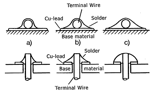
Right Amount of Solder![]() a) Minimum amount of solder
a) Minimum amount of solder![]() b) Optimal
b) Optimal![]() c) Excessive solder
c) Excessive solder

Solderability![]() a) Bad solderability of terminal wire
a) Bad solderability of terminal wire![]() b) Bad soldering of PCB
b) Bad soldering of PCB![]() c) Bad soldering of terminal wire and PCB
c) Bad soldering of terminal wire and PCB

Key Points to Remember
Summary
Operator training and
experience will, over time, provide the consistency needed for excellent hand
soldering results. Part of the training includes a proper understanding of
solder characteristics, how a soldering iron works, how to maintain tips,
correct techniques, recognizing good solder joints, and potential problems.